Tel/fax.: +7 (7112) 51-36-88, 50-79-09, +7 771 014 92 92
E-mail: info@agrs.kz
Automated Gas Distribution Station (AGDS)

Automated Gas Distribution Stations: Application
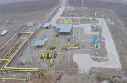
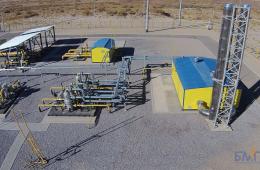
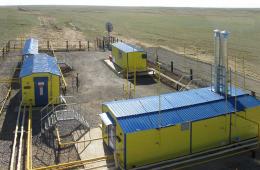
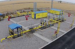
AGDS - is designed to reduce a high pressure of natural and associated petroleum gas to the specified low pressure and its maintenance with a required accuracy as well as for gas flow heating, purifying, metering and odorization before supplying to human settlements, industrial plants and other consumers. AGDS is reliable in operation and has a required redundancy of main technological processes as well it has an up-to-date automatic control system (ACS) of GRS.
AGDS — is a high-tech equipment that allows to cut of expenses and safe time for assembly, installation and commissioning work as well as to change old GDS and to construct new gas supply facilities.
AGDS range is constantly modernizing on the basis of a regularly remark and suggestion analysis of the specialists from operating organizations. The AGDS modular structure allows fully meet the consumers’ requirements in configuration and design.
AGDS Configuration
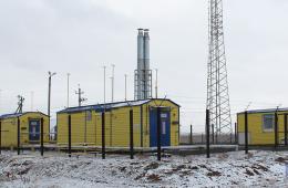
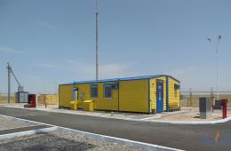
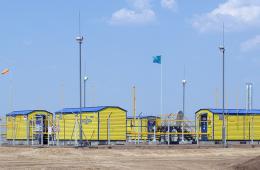
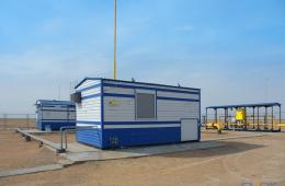
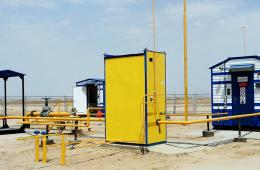
AGDS are supplied as a ready-to operate modular units that help to safe time for installation and commissioning work.
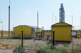
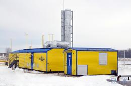
All equipment is in units of standard and northern trims as well they have the second grade of fire resistance. These units can resist to 9 magnitude earthquake. The units are made from a supporting metal frame that is a framing structure. The inner and outer roof and the walls of this frame are covered by metal sheets (corrugated sheet metal or metal siding) with a heat-insulating material. These units are equipped by an emergency input and exhaust ventilation that is actuated when an air pollution detector switches on. As well these units have an unauthorized entry alarm.
These units are heated by radiators that receive heat from the boilers located inside a gas heating unit. The dimensions of the units are evacuable to be transported by rail, land and sea.
BatysMunaiGazZhabdyktary, LLP manufactures and supplies AGDS of different gas flowrate on the basis of project statement and specifications.
AGDS functions:
- gas purification from dropping liquid and mechanical impurities with automatic condensate drain;
- preheating of the gas before its reduction and automatic maintenance of the set temperature to increase reliability of the equipment operation;
- reduction of the high pressure gas to the specified low pressure and maintaining it with the specified accuracy during the input pressure or gas flow rate changes;
- measurement of gas consumption with a long-term data recording and transmission to the level of the gas distribution organization;
- gas odorization;
- automatic control of the operating modes of the technological equipment at the station, including the restriction of gas supplies according to the requirements of the gas distribution organization;
- sound and visual alarm in case of emergency situations, as well as in case of any problems in signal transmission to a controller or an operator;
- removal of condensate from the condensate collection tank, transfer of the odorant to the odorization unit from the underground tank, nitrogen purging of the station nodes;
- autonomous power supply (including backup power from a gas generator, backup power from a transmission line through a transformer);
- water heating in all units of the station;
- gas supply to own needs.
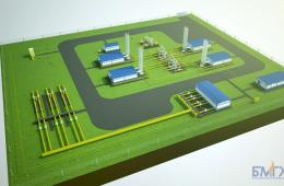
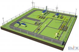
AGDS includes the following units:
Switching Unit is designed to:
Switching Unit is designed to:
- Disconnect the gas distribution station from a gas pipeline branches and outlet gas pipelines;
- Change the direction of the high pressure gas flow to a bypass line.
Downstream, a bypass line is equipped with a manual or automated valve and a gate valve with a manual or electric drive. Along the bypass line gas can be supplied both manually or automatically with the help of ACS GDS;
- To protect a consumer against excessive pressure in gas supply lines to the consumer.
Consumer protection against gas overpressure is provided by a safety relief valve unit that includes working and backup valves and a switching device (three-way valve), as well as gas blow-off lines.
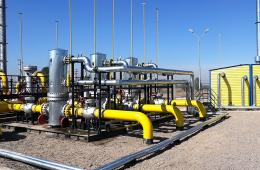
The switching unit is equipped by the following technological devices:
- switching node;
- safety valve assembly;
- bypass (backup) line;
- unit of filter-driers for pulsed gas preparation for valves with pneumatic drives;
- device of nitrogen technologies;
- pressure and temperature sensors;
- pressure manometers;
- insulating joints on the inlet and outlet pipelines.
The switching unit consists of inlet and outlet pipelines, pneumatically operated valves on the pipeline inlet and outlet and pneumatically operated gas vent valves.
Process Control Unit (Package)
A Process Control Unit is equipped by:
A Gas Purification Unit has a working and a reserve filters with a sharable storage tank. When purgings reach the upper limit of this tank they are automatically discharged to a condensate collection vessel. The degree of filter contamination is determined by a differential pressure sensor. To purify gas from mechanical impurities and droplet moisture both gas purification filters of FS (filter separator) and PCT (cyclone dust collector) types of our own production are applied.
Gas Flow Metering Unit. Depending on a measuring method and configuration of this unit, various components can be applied: orifice plates, turbine, vortex, ultrasonic or rotary meters. Gas flow metering can be carried out both at a high-pressure side (before reduction) and at a low-pressure side (after reduction);
A Gas Pressure Reduction Unit has two reduction lines (main and backup) with 100% flow each. If it is necessary to limit gas flow in the reduction unit, a controller with an electric drive or a regulator are installed. These devices are controlled remotely (upon a command from a control center of an operating organization) to limit gas flow to a consumer. Every reduction line has one working and one protective regulator. The applied pressure regulators automatically maintain the pressure with the accuracy of ± 5% regardless of inlet pressure and consumer’s gas flow fluctuation. If the operating parameters deviate beyond the permissible limits, a backup reduction line is automatically switched on. If it is necessary the reduction unit has a low-pressure line that is provided for operation in the initial period of AGDS operation.
A Gas Heating Unit is designed to warm up gas that is supplied to the reduction lines to the temperature from +5°С to +10°С at the outlet of AGDS. Coolant is an aqueous solution of ethylene glycol. Safety shut-off valves are installed at the inlet and outlet of the heat exchanger. These valves protect coolant supply system from increasing pressure in the event of a gas leak into a water jacket of the heat exchanger.
A Gas Pressure Reduction Unit for own needs (a gas heater, a boiler, an operator’s unit) is to be in an accessible place. Our Plant team designed a gas control unit (GCU) of different flowrate. Gas pressure at the GCU inlet is 2 – 2.5kPa. To prevent direct contact of natural gas and atmospheric air in “Goluboye Plamya” AGDS, there is a possibility to purge the AGDS pipelines with nitrogen during repair and maintenance operations. Nodes of nitrogen technologies for purging process lines can be placed in the switching unit and process control units.
The Gas Pressure Reduction Unit provides the following processes:
- mode automatic control of station process equipment;
- control, measurement, alarm and signaling functions;
- coordination of interaction between local automation systems;
- emergency protection in case of fire;
- emergency protection when the outlet pressure is exceeded;
- emergency protection when the level of gas odorization exceeds or falls below the nominal value;
- emergency signal transmitting to an operator and a dispatcher of the operating organization in case there are any problems in the operating mode of the AGRS.
ACS of GDS exchanges data with the dispatch center of the operating organization via a telemechanic channel. The choice of ACS GDS integration way into the telemechanic system is carried out at the stage of AGRS designing according to the Customer's specifications.
AGDS operative conditions
AGDS is designed for operation in areas with moderate and moderately cold climate (NF) as well as in regions with cold climate (F). A climatic category for AGDS is chosen depending on a construction area in accordance with the requirements of GOST 15150-69. AGDS can be installed in areas with seismicity of 8.0 on the Richter scale according to the P-7-81construction rules and regulations (SNiP). Design snow load of 200kgf/m2 conforms the requirements of the 5th territorial area and wind load of 85 kgf/m2 conforms to the 7th territorial area according to the SNiP 2.01.07-85.


